How it helps is the antiphase with increasing MAP can have a run away boost effect for the same level of duty so the control is not as accurate, especially on cars where TIP or more correctly MAP/TIP is not increasing in linear fashion with RPM after MAP peaks (stays flat for example). So the idea of an antiphase pressure sensor is to aid in making a programmable force air spring which then can help the control be more consistent gives more stable mechanical control and the software feedback is more effective.
So you're referring to normal phase/antiphase here or fill/empty? By antiphase pressure sensor do you mean capsule (top port) pressure? Confused because isn't antiphase usually bottom port?
Does having a regulated pressure source (co2 or compressor/accumulator) not combat the effect you speak of in itself?
In normal phase/antiphase you'd adjust your phase linearization to help combat the runaway effect.
I also struggle to see what a fill/empty setup does that a single 3 port doesn't? A single 3 port will apply pressure to the diaphragm or vent it.
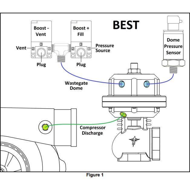
The fill empty installation pictured is an apparent contradiction of
http://www.syvecs.com/forum/viewtopic.php?f=14&t=292
With the fill solenoid de-energised, the NC port is holding back the boost or co2 pressure. With the fill solenoid energised the NC port of the empty solenoid is trying to contain the pressure in the top port.
However keep in mind for say a car with road orientation you do actually get very high TIP and TEP and instead of needing to run this or a idealized flat duty on the phase side and doing say bleed on control on the anti phase (depends on how you valves are set up) there is not much need to use this strategy complexity, cause you actually need to have the run away effect to counter the adverse conditions when TIP itself runs away.
TIP = turbine inlet pressure
TEP = ???
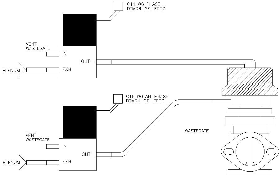
In a phase/antiphase setup are both solenoids not bleed on (I struggle to understand bleed on or off because surely whether the solenoid is applying pressure or bleeding it depends on the duty at the time)?
I'm talking about a restricted rally car with a load of boost low down and about 0.5 bar gauge by the end.
little side note: 25 years ago I designed some springs for a customer, wire diameter, number of coils to make his gates do the pressure he wanted. None of this is that hard, if I had to just rely on MAP I would make my own capsule, balance the area required to work with the available MAP range, and also select the WG valve area to work with the TIP maximum and put the wastegate near the end of the scroll on the turbine housing, locate the valves near the capsule and use right size ones along with lines of appropriate internal diameter and you would be shocked how much control range you would have, no need for bullshit compressed gas bottle in the car!
There must be something in it for WRC teams to do it. The weight and complexity of accumulator and/or compressor must be worth it as 'boxes were hydraulic. If you have compressor already for paddleshift then it makes little oddds.